Sunday, 1 April 2012

Take a picture with Arduino

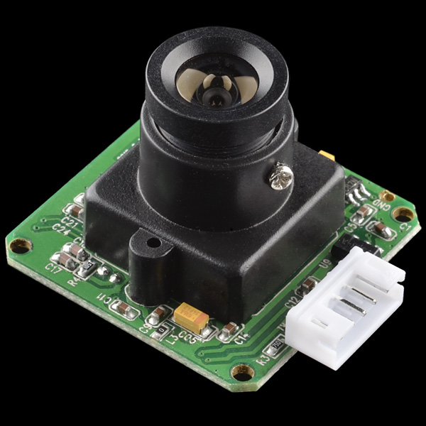
Have you ever thought to attach a camera on your Arduino? Well, today it's your lucky day because I can show you an example of you can connect the Linksprite camera to your Arduino.

Items:
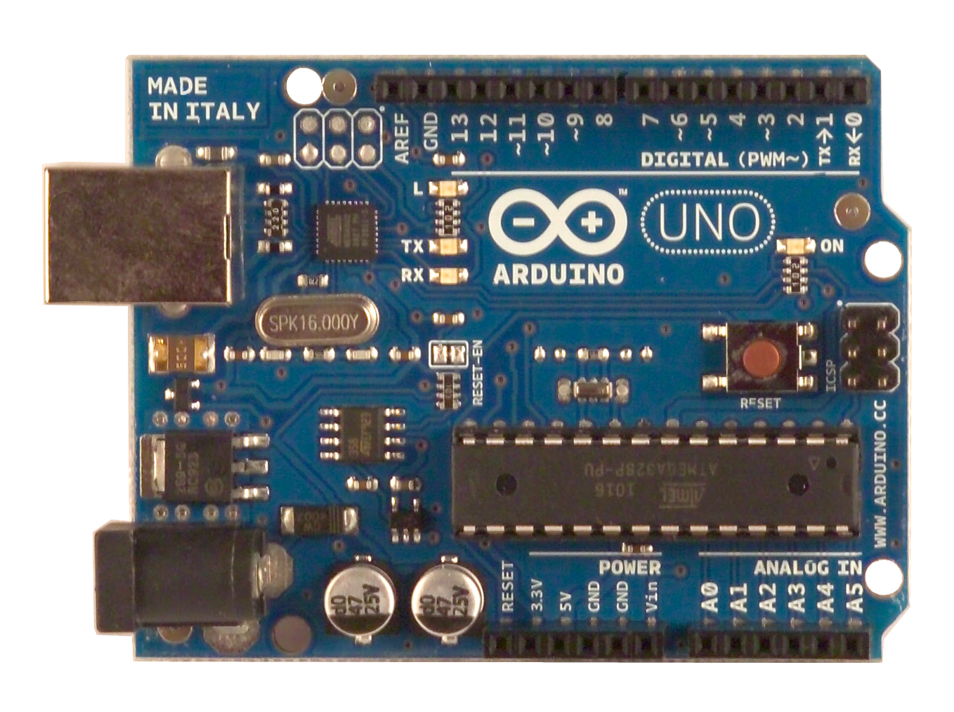
  1. Arduino uno
  2. Linksprite Camera JPEG
  3. SD Reader
Library:
  1. SD
  2. Adafruit VC0706 ( download )
 It's time to connect everything together! Connect your SD Reader as usually, I choose the SD Shield because it's simple to have everything in a pile, after that you can connect your camera on the pins 2,3.

2 => TX
3 => RX


When everything is connected, you need to open the Arduino IDE and try the example of Adafruit, make sure that the CS of the SD Reader it's the right one, otherwise you will not able to run the script.

You should see something like that:

When Arduino has finished to write the image on your SD Card, plug it on your computer and check the result.

**** ATTENTION *****
The example works only on Windows ( maybe OSX as well ).


Issue with Linksprite and Linux


Today, I want to create this article because I have been looking for a solution in 3 months.
The problem was with the magic Linksprite Camera JPEG, that you can buy on Sparkfun. This camera is a good solution to  have implement a camera on your project.
I was working on my project and I couldn't finish it because I found a problem with the communication between my Arduino and the Camera.


Basically every time that your turn on the camera you should receiver an INIT STRING:

VC0703 1.00
Ctrl infr exist
User-defined sensor
625
Init end

and in HEX codes is:
56 43 30 37 30 33 20 31 2E 30 30 0D 0A 43 74 72 6C 20 69 6E 66 72 20 65 78 69 73 74 0D 0A 55 73 65 72 2D 64 65 66 69 6E 65 64 20 73 65 6E 73 6F 72 0D 0A 36 32 35 0D 0A 49 6E 69 74 20 65 6E 64 0D 0A 

I was checking to get the same init when I was turning on the camera but I was getting something strange:
096A198136999B2C1C11514DE1E4AC90B457595CA82CAFD5175788AC6AD5E45AA4B2B32D6B455DAD5DCE6AFB98D859B498D21E189B7B45A48294BD5A4FC

How you see the result on Linux isn't right, is totally wrong!

I was looking for a solution on the internet, forum, etc... I found one post where a person was talking about the issue to compile the same code on difference OS, in particular that on Windows works and on Linux doesn't.


In the end I tried to use the same Arduino IDE on Linux and Windows and then I compared the result:


Windows:
056433037303320312E3030DA4374726C20696E6672206578697374DA557365722D646566696E65642073656E736F72DA363235DA496E697420656E64DA

Linux:
096A198136999B2C1C11514DE1E4AC90B457595CA82CAFD5175788AC6AD5E45AA4B2B32D6B455DAD5DCE6AFB98D859B498D21E189B7B45A48294BD5A4FC

Evidently there is something wrong on the Linux's compiler.
So, my solution now is to move the project on Windows and finally complete it.

I hope this article will help someone that has got the same problem.

Wednesday, 15 February 2012

Unlock door v1.0

INTRODUCTION
The project is an unlock door with Arduino that is using an intercom and a servo motor.
The reason of this project is that I wanted to open the main and flat door without using the keys, because in the winter it's too cool and the lock doesn't work properly ( I am just lazy :P ).
Fortunately the door is equipped with an intercom where from my flat I can unlock the door by pressing a button.


ITEMS
  • Arduino uno R3
  • Ethernet Shield
  • Relay
  • Servo
  • Ethernet cable
  • Webservice 
  • Own android app

DESCRIPTION
The project is using an Arduino to unlock the door, this is using a relay to make a bridge between two wires.
I made:

  • an Android app: you need to use this application to communicate to the Arduino with some web-services
  • a website: this is just a "proxy" and a security tunneling to send the right command to the Arduino, I am logging all the action that the users d.
I made a website because it was simply to make a kind of security and manager the user who could use it.

ENTRYPHONE
I opened the entryphone to understand how I can unlock the door, in my case was simple, I figured out that if I make a bridge between the GROUND and the UNLOCK WIRE I can unlock the door.

I extended the two wires outsite of the box to the relay and then I connected the relay to Arduino.


ANDROID APP
What I did it's a simple login screen and a second screen where I can check the status and send the command to unlock the doors.


ARDUINO
I looked in Internet how I can create a webserver with Arduino and I made a simple script to filter the GET request.
I did a TimerTask every 1 hour to update the IP on the website, because I don't have a static IP and I need to update it manually.

SECURITY
I choose to use the HMAC as security between Android -> Web -> Arduino,  I found a library to use with Arduino ( click here ).

LOG
The logs will be use to have a feedback who used the application and if there is any intrusion from unknown people.

VIDEO TEST

The first prototype


The final result


Tuesday, 5 July 2011

Fan controller

INTRODUCTION
The project is a fan controller, it's a simple remote switch power via IR.
In my case I am going to use the switch power to turn on/off a wall fan with a remote controller of the television.


ITEM

  • Fez Domino ( it's similar as Arduino but you code it in C# )
  • IR Receive Brakout
  • Relay 230V
  • Remote IR
  • Power BOX
DESCRIPTION
The project is using Fez Domino instead Arduino because I realized that this kind of platform it's too slowly and it good only for small project as this.
I figured out what is the code of a special button on the remote controller and I coded the Fez Domino to intercept it. When it intercept the IR code, it turns on or off ( status = ! actual status ) the Relay.

POWER
I recycled  a old Nokia power supply and it consume only 1.5 Watt.


VIDEO TEST


Monday, 13 June 2011

Progress

Dopo una lunga attesa ho convertito maggior parte del mio codice per Arduino.
I componenti sono funzionati subito al volo, non come per Fez Domino dove ho dovuto tribulare, ora l'unico intoppo è la camera che mi ritorna 1/4 dell'immagine.

Ho testato il modem gprs e sono riuscito a far muovere il servo da remoto, finalmente!


Monday, 30 May 2011

Arduino Uno

Overview

The Arduino Uno is a microcontroller board based on the ATmega328 (datasheet). It has 14 digital input/output pins (of which 6 can be used as PWM outputs), 6 analog inputs, a 16 MHz crystal oscillator, a USB connection, a power jack, an ICSP header, and a reset button. It contains everything needed to support the microcontroller; simply connect it to a computer with a USB cable or power it with a AC-to-DC adapter or battery to get started.
The Uno differs from all preceding boards in that it does not use the FTDI USB-to-serial driver chip. Instead, it features the Atmega8U2 programmed as a USB-to-serial converter.
"Uno" means one in Italian and is named to mark the upcoming release of Arduino 1.0. The Uno and version 1.0 will be the reference versions of Arduino, moving forward. The Uno is the latest in a series of USB Arduino boards, and the reference model for the Arduino platform; for a comparison with previous versions, see the index of Arduino boards.

Summary

MicrocontrollerATmega328
Operating Voltage5V
Input Voltage (recommended)7-12V
Input Voltage (limits)6-20V
Digital I/O Pins14 (of which 6 provide PWM output)
Analog Input Pins6
DC Current per I/O Pin40 mA
DC Current for 3.3V Pin50 mA
Flash Memory32 KB (ATmega328) of which 0.5 KB used by bootloader
SRAM2 KB (ATmega328)
EEPROM1 KB (ATmega328)
Clock Speed16 MHz

Problems and solutions

Ho constatato che il Fez domino non è adatto per questo genere di progetto, allora ho iniziato a comprare il mio nuovo controller, Arduino UNO.
Con l'Arduino ho un supporto migliore ed è più facile sviluppare a livello hardware, il Fez domino non è ancora pronto per questo genere di cose.

Come si puo trovare su internet, si puo prendere spunto su da questo progetto http://jayeshprojects.blogspot.com/2010/04/real-time-mobile-gps-tracker-with.html o vi sono librerie per aiutarti nello sviluppo.

Ora mi dedico alla riscrittura del codice per l'arduino.