Tuesday, 8 October 2013

Use Serial Port to access on your Raspberry Pi

Intro:
I was working on my personal project  where I couldn't attach a Ethernet cable to check what was going on or just check the status of my Raspberry Pi.
I knew that I could the pins TX and RX with a USB Serial port, so I got one and I started to use  as debug system.

Hardware:
You need a simple USB Serial port, you can get the cheap one here or you can get something "branded" on your usual electronic shop.

Wiring:
Connect the BLACK pin to the GROUND, the GREEN to the RX and the WHITE to TX.
If this combination wont work, just swap the GREEN and WHITE, it might be different from my adapter.

I never connect the red because your Raspberry is already powered from the usb port, so to avoid any problems, dont connect it!

Connection:
Everything is ready to communicate with your Raspberry Pi via Serial port, what you need to start, is a Terminal software, you can use GTK Terminal, Putty or whatever you prefer.

Open your software, select the right port, set the baud at 115200 and then you should see texts coming up on your terminal.


Sunday, 10 February 2013

Raspberry Pi and Leds strip RGB

Description
This project came up with my friend who wanted cover his room with leds strip and control all of them with a simple http request.
The idea was to be able to change color and the brightness, so I had to buy just a few components to make the controller:


  • 4x MOSFET N-Channel STP75NF75
  • 1x Breakout Adafruit
  • 1x 16 Channels servo Adafruit
  • 1x PCB
  • some wires

Schema
I just placed all my components on a PCB board, connected the 16 channels servo via I2C and each MOSFET to the leds strip.


Why MOSFET and 16 Channels?
Someone is maybe asking why I am doing this total mess with MOSFET.
The answer is that the 16 Channels couldn't give me the same result that I was expected. This means I couldn't pass the max power through this board, so I avoided the problem by using  4 MOSFET that are getting the main source power, 12V, and Raspberry is sending the right pulse to each ones.

HTTP Request
My friend made a little script in Python that is waiting for a POST request with Red, Green, Blu, Power as parameters and then it will send the new color through the 16 Channels.

Code?!
I don't really have so much code, I took the example from Adafruit to drive the 16 channels ( 3 lines ) and then parsed the 4 parameters to send the value between 0 and 4095.
Obviously I can post something if someones needs a little guide how to parse these values =).


Video


Saturday, 26 January 2013

Leds Strip Fading system


Description
I made a little test with some components to find out how to control the brightness of this leds strip, I couldn't find a good answer on Google so I came up with a solution.
Keep in mind that I am not an electronic so this solution could be not the best one, it worked and tested. 

Items
  • Leds strip
  • Arduino
  • N-Channel MOSFET, my was 2N7000
  • 200 ohm resistor
Schema


Code

void setup() {
    pinMode(5,OUTPUT);
    pinMode(6,OUTPUT);
}

void loop() {
 analogWrite(5,0);
 for (int i = 0;i < 260;i++) {
    analogWrite(6,i);
    delay(10);
 }
}

Saturday, 12 January 2013

Converting a freezer into a Lipton icetea dispenser

Introduction
This project could sound weird because why would I want to use a freezer instead of a fridge? why would I want to make a Lipton IceTea dispenser and what does it mean?
There are a lot of questions about this project and there are only two answers:

  1. My friend bought the wrong fridge to store some drinks but he only realised this when we got home. It wasn't a fridge but a freezer!
  2. We couldn't be bothered to get up, open a bottle and refill our glass, instead we prefered pressing a button and having our glasses automatically refilled.
If you want to reproduce this project you can avoid to buying a freezer instead buy a fridge and remove some other components.

Transforming a freezer to a fridge
I thought that the best option to don't waste more money and keep the bottle in a liquid state, is to control the temperature inside of the freezer. I got one temperature sensor DHT22 and attached a relay to the power socket, by doing this I could switch the power on and off when the temperature was too high or too low and the bottle didn't become a big block of ice.

Back of the freezer where was connected the sensor to turn on/off by the sensor of temperature

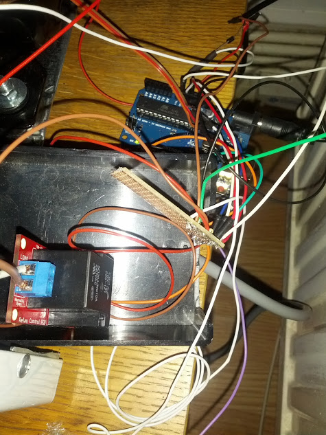
I connected the sensor and the relay to the Arduino, I made a little script that keeps it switched on because if the temperature drops below 5° to 0°C it stops working and becomes a freezer.
The two wires ( Brown and White ) are going to connect into the relay


IceTea distribution 
This is the most expensive part of the process, I had to make one hole on the fridge to ensure the pump works effectively. The tube is used to get the liquid from the freezer.

  • Holes
The freezer was not equipped with a hole to pass one hose, that means that I had to use a drill to make it. 
There is one hole, on the  lower part
To ensure that the warmth was not dispersed through these holes, I had to use some kind of isolant and I chosen the product Sugru.
  • Water pump
The pump was the main part of the project as it has to move the liquid from the fridge into the glass, but I had to make sure that the pump was FDA tested!
If you don't have a certificated pump , you could drink a poisoned liquid. 
I hadn't check this part of the project when I bought the pump( see the picture below ). Fortunately I found that it's very dangerous to buy the cheapest one because you didn't want to spend 10-20 pounds more.


In the end I had to contact the company TOPSFLO that had certificated pumps and I bought one for 30 pounds ( included the shipping cost ).
This was the pump ( website ):


To connect this pump with your Ardiuno, please have a look at this tutorial: http://bildr.org/2012/03/rfp30n06le-arduino/.
  • Hose
I bought two types of hoses, one of them is used to connect the bowl to the pump ( 13mm ) and the second one is connect the pump to outside of the fridge ( 9mm ).


I also bought a tap hat gourmet to fit the hose into the bowl, in that way I can take off the tube and wash the container without cutting anything. 

  • Push buttons
I have chosen to install two push buttons, the first one fills the glass in one shot and the other one is working as a normal button, when you press it the pump is working and when you release everything stops.


  • Valves
The system could work without any valves because there wasn't any problem of functionality, the only problem was that you wouldn't  drink something that was not isolate and kept into a bottle.
If I didn't use a valve, the liquid will be the same as leaving the bottle open in a fridge.

I found the non return valve for the external tube.


 Prototypes

Demo 1


Demo 2


How refill the fridge


Arduino messy wiring

The wiring was a little bit messy on the back of the fridge but I want to explain what I have connected there:

I have made a own PCB that I have attached:
  • MOSFET: switch the pump on/off
  • Resistents: DTH22 needs one and the pump
  • 5V and Ground: these two just to have a specific place to get the power and ground
I have connected the relay to the Arduino to turn on/off the fridge and 2 wires to get an analog input of the two buttons.


I had to make sure that all holes were isolated and for that I have used the awesome product Sugru that was a kind of silicon and it makes a perfect insulating.


Sunday, 6 January 2013

Webcam over 3G with Raspberry PI

Description
This project was about a personal challenge that my Dad asked me to do it.
Everything started more than one year ago when I was trying to do it with Arduino but I lost a lot of time because I couldn't make everything works as fast as Raspberry does.
I decided to move on Raspberry PI and everything became easy and fast, in a few days I had made 70% of the project.

Let's talk about the project, my idea was to create a remote webcam that I could control it over the 3G network, because I wanted to install it on my mountain's house and I don't have an internet connection.
The camera have to be equipped with:
  • 2 servos: move left/right and up/down from a web interface
  • one temperature sensor: getting information and store them in a file
  • one motion sensor: something like a little CCTV that will send me message and picture when someone is close to it
Obviously everything have to be very well thought for any little problems,  and in case that something goes wrong, I had to make sure that I can access to the camera and fix it.


Raspberry : http://amzn.to/2pQXDUw
Battery: http://amzn.to/2qeENrz
Camera: http://amzn.to/2pRgkr5

Simple Schema
Schema


Web Interface
I made a little website to communicate with the camera, I can move it LEFT/RIGHT and UP/DOWN by pressing 4 buttons.
I can get the current temperature, start live streaming, change motion alerts and manager all files about camera pictures and some other files.
I'd like to improve everything with a proper client side using another Raspberry Pi, small screen and a few buttons.


3G Modem
I was looking for a good and cheap 3G modem that could work with Raspberry PI and read/send message, what I found was the HUAWEI E3131 that had a web interface and a simple API to control it.
I made a little wrapper library that I could send commands from my Python code, something like: connect to 3G network, send message, read message, etc..
I really recommender this modem because it was cheap, unlocked and easy to use!

Python library for HUAWEI E3131


Servo Pan and Tilt
I had to build my own Pan and Tilt system because the position that I have chosen is not simple one.
I came up with a solution to put everything in a PVC tube and attached one servo on the top to move the whole structure and the second to move the camera up and down.

First prototype:


Webcam
I have used fswebcam to capture snapshot from the webcam and I made a little wrapper in Python to execute this command with specific parameters.


Temperature sensor
I have chosen the DHT22 as temperature sensor, because it was easy to hook up with Raspberry and I have used this sensor on my previous projects with good results.
What I thought was to implement this sensor to store different temperatures through the whole year and have a little chart about the weather on my mountain.

Motion sensor
The motion sensor was attached to my Raspberry via one digital pin, there was a thread that was checking every 4 seconds if someone was there and send me two kind of alert: SMS and upload the picture.
I have implemented some functions to remove any kind of alert in case that the motion sensor will be trigger for stupid reasons.

AutoSSH
This was my special army to access on my Raspberry even if I was connected to a 3G network, because you know that you can't open any port as you can do on your own modem.
Basically I had to setup a ssh key to connect to my server without insert the password and create a system to active and de-active the session.
I came up with an external service with Python that will start the service if the internal service was crashing. You never know if the main script will working properly or your thread will stop to work, so this was my second security system to access and fix it.

External Power
Raspberry has only one micro usb port to give power to the whole system, so I had to solder 2 wires directly to the board.
I found the instruction on this website: http://www2.pmb.co.nz/blog/computers/raspberry-pi-direct-5v-power-wiring-modification/ to understand which pins were the 5+ and GND.
I suggest to mount  a fuse between the battery and the Raspberry, in case that something goes wrong and you don't burn your board.


Solar panel
The power source was a little problem because at 2'000 meters over the sea you don't have a normal power socket to plug your devices, so I bought a solar panel from EBay and a car battery.
I have chosen the car battery because you have 2 years of warranty and I was looking for something very high capacity and I found one with 55mAh at 12V.


Conclusion
I am testing this configuration at home before move everything at 2'000 meters, so I can be sure that at least for a month I can connect to it, get some pictures and fix any crashes that will came up.


Friday, 14 December 2012

Red carpet's project


Description
The red carpet's project was an interactive installation that my company wanted to build for the Christmas party.
Basically the idea was to create a little interactive space where people could walk through this red carpet and some paparazzi would display on the wall.
This wasn't enough to make an amazing experience, so we decided to implement 24 leds around the area where the video was projected and flashed all of them like a real flash.
We also decided to implement an area to take a picture of  yourself and display it into the slideshow.

Video presentation
LEDs matrix
I have builded 6 panels of leds and a big bus of 24 cables to control all leds, I chosen to use a transistor and an external power supply to light all of them, and also a shift register to control them.
This was the shift register with 24 outputs
Each panel have a "home made connector" to make the installation easier and comfortable to carry.

These were 5 panels when I was testing them

My little PCB with led and transistor

Pressure Mat
I have connected 2 pressure mats on my Arduino that have two pins to make it works, one ground input and the output to detect you have triggered it, you can buy them here .
When you step on the first mat the paparazzi movie starts and all 24 leds are starting to flash randomly. And then when you reach the second one, it triggers the count down to make the pose and display it on the slideshow.

Camera trigger
The camera trigger was made with openFramework and the Canon's SDK.
This part wasn't made by me but I have made a similar program with Processing that does the same.
More information about Camera and animation integration are posted to this link

Result
The final installation, its missing some decoration to cover all wires and tapes


We are enjoying the red carpet :)

Even with a lot of people it was a great experience 


Video


People are enjoying the experience:


Testing some leds with a random sequence:


General overview of the installation:


Little tour after I finished to wire up:


Monday, 10 December 2012

First steps with Raspberry PI

Introduction
I have got my first Raspberry PI last week and I started to discover this beautiful world but I am a little bit upset about low level connection.


These are the bad things:
- You can't read from an analog input if you don't buy a board that helps you to get this information ( click here ).
- You can't move 2-3 servos if you don't buy a 16 channel servo driver ( click here ).
At least there are some solutions to pimp your Raspberry PI :)


My first steps
I have decided to move my old and unfinished Arduino project to Raspberry PI and after 2 days of working I have done a lot of work that Arduino takes a lot of time.
I never tried to connect something to a digital pin and I thought that was simple as Arduino, but when I was looking for the right pin, I couldn't understand from the board which one was the right one.
I had to looking for the schema of Raspberry and found out each digital pin, that it's silly because they could put something like GPIO 1, GPIO 2, just next to each pin.

In the end I am connected my DHT 22 ( temperature sensor ) to the pin GPIO 4 and installed a little script in C, because Python is not faster enough to get the data. This is the guide that I followed (click here).