Friday, 25 October 2013

Photo resistor with inverter logic


Intro:
I was looking for a system that allowed me to trigger a circuit when was getting dark, so I found out that with some testing, a photo resistor and a inverter logic I could achieve this goal.

Items:

  • 1x 74HC04N ( hex logic )
  • 1x photo resistor
  • few resistors ( 10-22k )
  • 1x transistor n-channel
  • 1x led
  • 1x battery 5v
  • few jumpers

Wiring:


Connect the battery to the VCC and Ground of your Inverter logic.
The photoresistor needs to be connect to 5v on one pin and the other needs a resistor 10-22k to the ground and a jumper to the Input 1 on your Inverter logic. The resistor has to be tested on the final circuit because based on it, the system trigger the transistor when is very dark or less dark.
Connect the output 1 on the gate of your transistor, the drain to the led and the source on the ground. Remember to bridge the gate and source with 10k!
Complete everything by connecting the other pin of the led to the 5v, better to put a resistor if you dont want burn it.

After all this is done, try to cover it or switch off your light, you should see the led lighting up, if it doesn't work, try with something less than 10k.


Video:


Monday, 21 October 2013

Blinking leds with 555 timer

Intro:
I was looking for something that could make some leds blinking, but my head always ended up with some Arduino stuff.
I had to move my challenge to the next level, forget about the helpful Arduino and move to the real electronic way!
After few hours of research I came up with the 555 timer solution, simple, clean and cheap.

Items:

  • 555 Timer
  • Capacitor ( try to get a few from 10 to 100 uF )
  • Resistor 
  • Leds
  • Battery

Wiring:


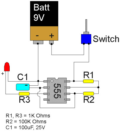
The diagram above is the simplest one that I found in the internet, it shows how to connect the 3 resistors, capacitor and led.

Tweaking:
Here we go, now we have our flashing system but you have to tweak it a little bit because the flashing delay is too higher or lower for your project.
Change the capacitor with something higher than 100 uF to increase the delay or something lower to decrease the delay. 

Here an example:
100 uF = 2 flash per seconds
10 uF = 10 flash per seconds 
These are just "fake" information, but you can have an idea which capacitor you have to use for your project!

The brightness of the led can be changed by using the current resistor on R3, maybe 1K is too higher for your type of light.

The flashing delay can be adjust by changing the R1 and R2 with lowers values, but be careful, better have a look on the internet and calculate the right ones!

Sunday, 20 October 2013

Smoking Pumpkin


Items:

  • Pumpkin
  • Tray ( the right size of your pumpkin )
  • Glycerin
  • Water de-ionized 
  • Tea lights
  • Nails

Construction:


  1. Get a Pumpkin and create your scary face and cut the top to have access to the inside


  2. Put 4 nails on the inside of your Pumpkin, the position of each has to be good for your tray, so make sure that is not too far.
  3. Put as many as tea lights you can fit, more there are, less time you have to wait to get some smoke
  4. Get your Tray and put 60% Glycerin and 40% Water to have good and thick smoke.
    If smoke is too thick, reduce the amount of Glycerin and add more water, you should try until you find out what is the best for you.
    Better if you close the Pumpkin, so the heat doesn't go away.
  5. Place your Pumpkin smoking outside in the dark and enjoy the smoke effect!


Reference:


Sunday, 13 October 2013

Happy Birthday Box

Intro:
I had to buy a present for a my friend but I didn't want to come up with something useless and out-fashion, so I thought to use my skills in electronic to build something different.
My mind made some wired ideas and I ended up with a "Happy Birthday box".

What Does It Do?
The Happy Birthday Box is a simple project where a small Arduino, LCD Screen, Buzzer and a battery are used to wish Happy Birthday with sound and text.
I had to mount a little switch to turn on the whole system, nobody wants the infinite Happy Birthday song on his house :)

Hardware:
I ordered these items:

  • Arduino mini ( you can use any Arduino
  • LCD Screen ( 16x2 )
  • Buzzer
  • Booster battery ( from 3.7 to 5v )
  • Battery 3.7 850mah
  • Roller switch

Wiring:

LCD:
This is a pretty simple way to wiring the LCD screen, they are all the same, the only issue that I have seen so far is to choose the right resistor for the contrast.
I have seen tutorials tell me to use 10 ohm but in my case I couldnt use this one, I had to increase to 600 ohm to actually read something on the screen. So be careful, if you dont read what you are trying to display, is not always a wiring problems! 

I just redirect to this nice guide how to wiring your LCD: http://arduino.cc/en/Tutorial/LiquidCrystal
If you want to get rid of the potentiometer, just put try to put some resistant from pin RS ( LCD ) to GND ( LCD ).
Also to light up the back light of the screen, just solder the penultimate pin to 5V and the last pin to the ground with 100 ohm ( usually is written + and - in the back ).
   

Buzzer:
Very simple, just attach the ground and the other cable to one of the pin.

Code:
Very simple and "clean" ( I hope ), I haven't written the melody part, I just got from internet:

Tuesday, 8 October 2013

Use Serial Port to access on your Raspberry Pi

Intro:
I was working on my personal project  where I couldn't attach a Ethernet cable to check what was going on or just check the status of my Raspberry Pi.
I knew that I could the pins TX and RX with a USB Serial port, so I got one and I started to use  as debug system.

Hardware:
You need a simple USB Serial port, you can get the cheap one here or you can get something "branded" on your usual electronic shop.

Wiring:
Connect the BLACK pin to the GROUND, the GREEN to the RX and the WHITE to TX.
If this combination wont work, just swap the GREEN and WHITE, it might be different from my adapter.

I never connect the red because your Raspberry is already powered from the usb port, so to avoid any problems, dont connect it!

Connection:
Everything is ready to communicate with your Raspberry Pi via Serial port, what you need to start, is a Terminal software, you can use GTK Terminal, Putty or whatever you prefer.

Open your software, select the right port, set the baud at 115200 and then you should see texts coming up on your terminal.