Friday 14 December 2012

Red carpet's project


Description
The red carpet's project was an interactive installation that my company wanted to build for the Christmas party.
Basically the idea was to create a little interactive space where people could walk through this red carpet and some paparazzi would display on the wall.
This wasn't enough to make an amazing experience, so we decided to implement 24 leds around the area where the video was projected and flashed all of them like a real flash.
We also decided to implement an area to take a picture of  yourself and display it into the slideshow.

Video presentation
LEDs matrix
I have builded 6 panels of leds and a big bus of 24 cables to control all leds, I chosen to use a transistor and an external power supply to light all of them, and also a shift register to control them.
This was the shift register with 24 outputs
Each panel have a "home made connector" to make the installation easier and comfortable to carry.

These were 5 panels when I was testing them

My little PCB with led and transistor

Pressure Mat
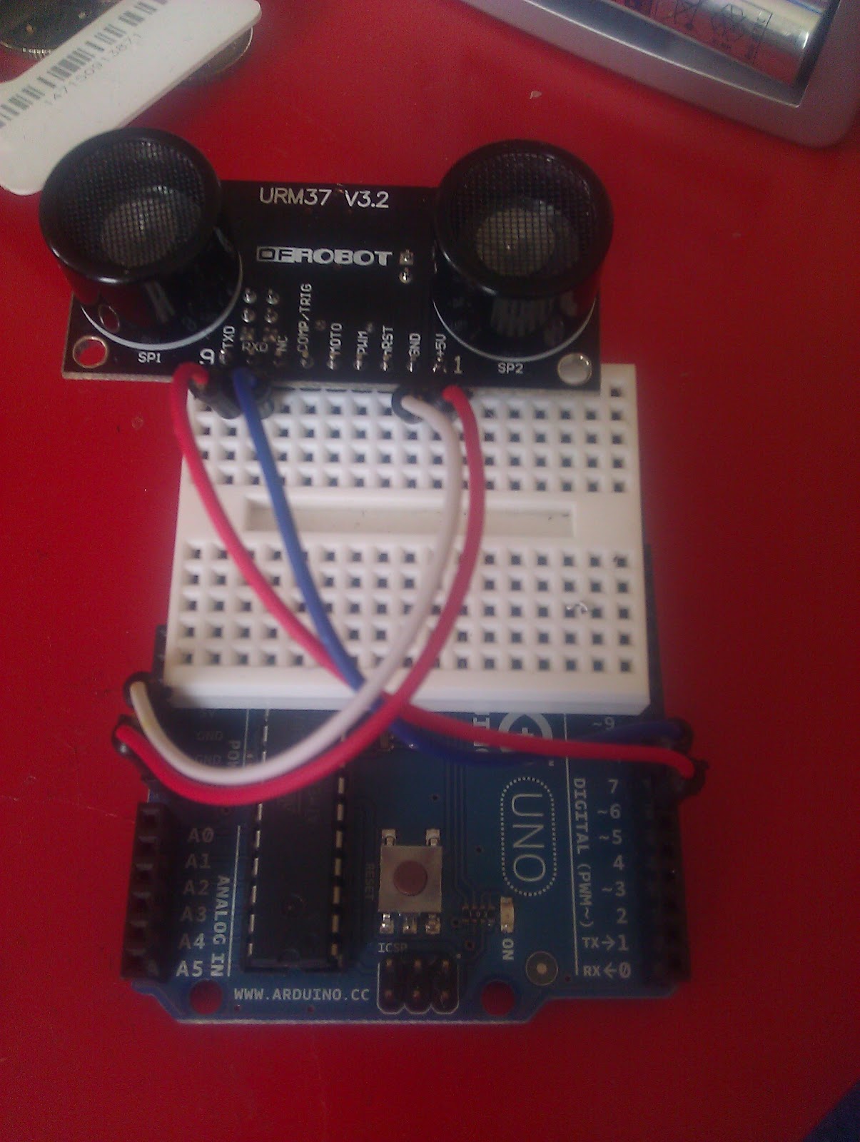
I have connected 2 pressure mats on my Arduino that have two pins to make it works, one ground input and the output to detect you have triggered it, you can buy them here .
When you step on the first mat the paparazzi movie starts and all 24 leds are starting to flash randomly. And then when you reach the second one, it triggers the count down to make the pose and display it on the slideshow.
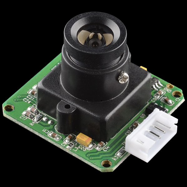
Camera trigger
The camera trigger was made with openFramework and the Canon's SDK.
This part wasn't made by me but I have made a similar program with Processing that does the same.
More information about Camera and animation integration are posted to this link

Result
The final installation, its missing some decoration to cover all wires and tapes


We are enjoying the red carpet :)

Even with a lot of people it was a great experience 


Video


People are enjoying the experience:


Testing some leds with a random sequence:


General overview of the installation:


Little tour after I finished to wire up:


Monday 10 December 2012

First steps with Raspberry PI

Introduction
I have got my first Raspberry PI last week and I started to discover this beautiful world but I am a little bit upset about low level connection.


These are the bad things:
- You can't read from an analog input if you don't buy a board that helps you to get this information ( click here ).
- You can't move 2-3 servos if you don't buy a 16 channel servo driver ( click here ).
At least there are some solutions to pimp your Raspberry PI :)


My first steps
I have decided to move my old and unfinished Arduino project to Raspberry PI and after 2 days of working I have done a lot of work that Arduino takes a lot of time.
I never tried to connect something to a digital pin and I thought that was simple as Arduino, but when I was looking for the right pin, I couldn't understand from the board which one was the right one.
I had to looking for the schema of Raspberry and found out each digital pin, that it's silly because they could put something like GPIO 1, GPIO 2, just next to each pin.

In the end I am connected my DHT 22 ( temperature sensor ) to the pin GPIO 4 and installed a little script in C, because Python is not faster enough to get the data. This is the guide that I followed (click here).


Thursday 28 June 2012

URM37 Proximity sensor

This article talks about the awesome URM37 V3.2 proximity sensor by DFRobot, I want to show you what are the steps to make it working because when I was looking for this I couldn't find a good tutorial and I became frustrated when the sensor didn't work.


Jumpers
This sensor has 3 jumpers on the back, you need to change the position of them as the picture below shows:
This configuration is to enable the TTL connection. If you don't change it before to connect your Arduino, you will damage the sensor. 


Wiring
The wiring of this sensor is very easy, you need to connect 4 cables in this sequence:

  • Sensor TX     =>    Arduino pin 6
  • Sensor RX     =>    Arduino pin 7
  • Sensor 5v       =>   Arduino vcc
  • Sensor GND  =>   Arduino GND

and you should see something like this:


Code
You have to download a library that is made for this sensor, Library from Lauren(Only Arduino IDE 1.0), this library should work without any problem but you need to comment 2 lines before to using it.
Open the URMSerial.cpp and URMSeral.h and then comment the line #include <HardwareSerial.h> otherwise your Arduino will give you some errors of compiling.

Ok, we are ready to test the first example that DFRobot made for us, just open this link and push it on your Arduino and then you will see something like this:


If you are getting the result ERROR everytime and you don't see any number, try the following:

  1. Check your wiring, maybe you didn't connect your sensor very well
  2. Your sensor is broken and you should contact DFRobot to replace this item

Saturday 9 June 2012

Processing and Arduino

INTRODUCTION
I was thinking about this opportunity to communicate between Processing and Arduino and I made a simple example that I get a visual feedback from a light sensor.
The idea is to create a scenery and change it depending on the value of the sensor. Basically show the sun with a brightness color when there is a lot of light and then show the moon with a dark background  when there isn't enough light.

PROCESSING
What you need is the Processing IDE and try to play with it, create a scenery and some animation.
What I did is a simple animation of moving a circle up and down, and then change the background color.
As soon as you have something working, you need to implement Firmata for Processing  (http://www.arduino.cc/playground/Interfacing/Processing).

***I found an issue with Linux, if you want to communicate with your Arduino, you need to make sure that  with your Arduino IDE works and then lunch this command:

sudo ln -s /dev/ttyACM3 /dev/ttyS42
ACM3 = Arduino port
ttyS42 = This port will be use on processing

You need to change your connection line to something like that:
 arduino = new Arduino(this, "/dev/ttyS42", 57600);

Otherwise if you are Windows user you need to write something like that:
  arduino = new Arduino(this, Arduino.list()[0], 57600);
[0] = Try to change the number zero with something else if you are getting some connection errors.

I want to tell you the truth, you are going to think that Processing is another complicate language and you will never use it, NO that is absolute wrong, I made this project in about 2 hours, Processing is very simple and you can find a lot of examples and libraries.


ARDUINO
You need to upload on your Arduino the Standard Firmata that is on your example menu.
Ok, the last step is to connect your device on your Arduino, I bought a light sensor that works with an analog pin and I attached it on the pin A0.

Change your Processing example to get the value , in my case the command to get the analog input was:
arduino.analogRead(0);

EXAMPLE
This is my example that I made with Processing and Arduino, you can check the video on the bottom, please don't care about my design skills :).


import processing.serial.*;
import de.looksgood.ani.*;
import cc.arduino.*;
import guicomponents.*;

//sudo ln -s /dev/ttyACM3 /dev/ttyS42
//Pin A0
Arduino arduino;

color off = color(4, 79, 111);
color on = color(84, 145, 158);

float sunX = 800, sunY = 100;
float moonX = 800, moonY = 800;
int light = 50;
float lightMoon = 0, lightSun= 0, lightSky = 191, lightSky2 = 255;
GWSlider sdr1;

int a = 0;

void setup() {
  size(1024, 800);
  arduino = new Arduino(this, "/dev/ttyS42", 57600);
  Ani.init(this);
  sdr1 = new GWSlider(this,20,20,260);
  sdr1.setLimits(0, 0, 1000);
}

void draw() {
  background(0, lightSky, lightSky2);
  stroke(on);
  displaySheme(light);
  showVillage();
  light = arduino.analogRead(0);

  fill(0, 102, 153);
  text("Current light: "+light,50,780);
}

void showVillage() {
  //Draw the grass
  fill(50, 205, 50);
  rect(0, 600, 1024, 200);
  //Draw the house
  stroke(off);
  fill(139, 69, 19);
  rect(100, 450, 160, 200);

  fill(211, 211, 211);
  rect(120, 480, 50, 50);
  rect(190, 480, 50, 50);

  rect(160, 580, 50, 70);

  fill(193, 205, 193);
  triangle(100, 450, 180, 400, 260, 450);
}

void showSun() {
  fill(255, 255, lightSun);
  ellipse(sunX, sunY, 100, 100);
}

void showMoon() {
  fill(255, 255, 255);
  ellipse(moonX, moonY, 100, 100);
}

void displaySheme(int light) {
  float newY = constrain(map(light, a, 100, 1100, 100), 100, 1100);
  float newC = constrain(map(light, a, 100, 255, 0), 0, 255);
  float newB = constrain(map(light, a, 161, 0, 255), 0, 255 );

  if (newY > 600) {
    Ani.to(this, 1.5, "sunY", newY);
    Ani.to(this, 1.5, "lightSun", newC);
    sunY = 700;  
    Ani.to(this, 1.5, "moonY", 100);
  }
  else {
    Ani.to(this, 1.5, "sunY", newY);
    Ani.to(this, 1.5, "lightSun", newC);
    Ani.to(this, 1.5, "moonY", 700);
  }
  //change the sky
  Ani.to(this, 1.5, "lightSky", newB);
  Ani.to(this, 1.5, "lightSky2", newB);
  showSun();
  showMoon();
}

void handleSliderEvents(GSlider slider) {
  a = slider.getValue();
  println("integer value:" + slider.getValue() + " float value:" + slider.getValuef());
}


VIDEO


Wednesday 23 May 2012

Issue with Wifly and LCD Screen

Problem

The issue is with the Sparkfun Wifly (http://www.sparkfun.com/products/9954) and Sparkfun LCD screen (http://www.sparkfun.com/products/9363), I was using the Wifly Library and ColorLCDShield Library.
When you want to connect everything together you will not be able to communicate with the LCD after you initialized the Wifly, that because for some reason the SPI bus still communicate with the Wifi.

Solution

The fix is quiet simple, you need to modify 6 files of the Wifly Library:

_Spi.h
//Add two new methods
void end();
void restore();

_Spi.cpp
//That will disable the SPI
void SpiDevice::end() {
SPCR = 01010000;
}

void SpiDevice::restore() {
_initSpi();
}

SpiUart.h
//Add two new methods
void end();
void restore();

SpiUart.cpp
void SpiUartDevice::end() {
SpiDevice::end();
}

void SpiUartDevice::restore() {
SpiDevice::restore();
}

WiFlyDevice.h
//Add two new methods
void end();
void restore();

WiFlyDevice.cpp
void WiFlyDevice::end() {
uart.end();
}
void WiFlyDevice::restore() {
uart.restore();
}

Example

//Start the connection with the Wifly
WiFly.begin();
  
  if (!WiFly.join(ssid, passphrase)) {
    Serial.println("Association failed.");
    while (1) {
      // Hang on failure.
    }
  }  

//Stop for a moment the connection between the SPI and Wifly
WiFly.end();

//Do something with the LCD
lcd.init(PHILLIPS);    //Initialize the LCD
lcd.contrast(40);   // Sets LCD contrast, adjust this if your contrast is odd looking.
lcd.clear(WHITE);    // Clear LCD to solid white

//Restore the communication with the Wifly
WiFly.restore();

So, every time that you want to communicate with the LCD screen, you need to end the SPI communication and leave that to the LCD screen.

Sunday 1 April 2012

Take a picture with Arduino

Have you ever thought to attach a camera on your Arduino? Well, today it's your lucky day because I can show you an example of you can connect the Linksprite camera to your Arduino.

Items:
  1. Arduino uno
  2. Linksprite Camera JPEG
  3. SD Reader
Library:
  1. SD
  2. Adafruit VC0706 ( download )
 It's time to connect everything together! Connect your SD Reader as usually, I choose the SD Shield because it's simple to have everything in a pile, after that you can connect your camera on the pins 2,3.

2 => TX
3 => RX


When everything is connected, you need to open the Arduino IDE and try the example of Adafruit, make sure that the CS of the SD Reader it's the right one, otherwise you will not able to run the script.

You should see something like that:

When Arduino has finished to write the image on your SD Card, plug it on your computer and check the result.

**** ATTENTION *****
The example works only on Windows ( maybe OSX as well ).


Issue with Linksprite and Linux


Today, I want to create this article because I have been looking for a solution in 3 months.
The problem was with the magic Linksprite Camera JPEG, that you can buy on Sparkfun. This camera is a good solution to  have implement a camera on your project.
I was working on my project and I couldn't finish it because I found a problem with the communication between my Arduino and the Camera.


Basically every time that your turn on the camera you should receiver an INIT STRING:

VC0703 1.00
Ctrl infr exist
User-defined sensor
625
Init end

and in HEX codes is:
56 43 30 37 30 33 20 31 2E 30 30 0D 0A 43 74 72 6C 20 69 6E 66 72 20 65 78 69 73 74 0D 0A 55 73 65 72 2D 64 65 66 69 6E 65 64 20 73 65 6E 73 6F 72 0D 0A 36 32 35 0D 0A 49 6E 69 74 20 65 6E 64 0D 0A 

I was checking to get the same init when I was turning on the camera but I was getting something strange:
096A198136999B2C1C11514DE1E4AC90B457595CA82CAFD5175788AC6AD5E45AA4B2B32D6B455DAD5DCE6AFB98D859B498D21E189B7B45A48294BD5A4FC

How you see the result on Linux isn't right, is totally wrong!

I was looking for a solution on the internet, forum, etc... I found one post where a person was talking about the issue to compile the same code on difference OS, in particular that on Windows works and on Linux doesn't.


In the end I tried to use the same Arduino IDE on Linux and Windows and then I compared the result:


Windows:
056433037303320312E3030DA4374726C20696E6672206578697374DA557365722D646566696E65642073656E736F72DA363235DA496E697420656E64DA

Linux:
096A198136999B2C1C11514DE1E4AC90B457595CA82CAFD5175788AC6AD5E45AA4B2B32D6B455DAD5DCE6AFB98D859B498D21E189B7B45A48294BD5A4FC

Evidently there is something wrong on the Linux's compiler.
So, my solution now is to move the project on Windows and finally complete it.

I hope this article will help someone that has got the same problem.

Wednesday 15 February 2012

Unlock door v1.0

INTRODUCTION
The project is an unlock door with Arduino that is using an intercom and a servo motor.
The reason of this project is that I wanted to open the main and flat door without using the keys, because in the winter it's too cool and the lock doesn't work properly ( I am just lazy :P ).
Fortunately the door is equipped with an intercom where from my flat I can unlock the door by pressing a button.


ITEMS
  • Arduino uno R3
  • Ethernet Shield
  • Relay
  • Servo
  • Ethernet cable
  • Webservice 
  • Own android app

DESCRIPTION
The project is using an Arduino to unlock the door, this is using a relay to make a bridge between two wires.
I made:

  • an Android app: you need to use this application to communicate to the Arduino with some web-services
  • a website: this is just a "proxy" and a security tunneling to send the right command to the Arduino, I am logging all the action that the users d.
I made a website because it was simply to make a kind of security and manager the user who could use it.

ENTRYPHONE
I opened the entryphone to understand how I can unlock the door, in my case was simple, I figured out that if I make a bridge between the GROUND and the UNLOCK WIRE I can unlock the door.

I extended the two wires outsite of the box to the relay and then I connected the relay to Arduino.


ANDROID APP
What I did it's a simple login screen and a second screen where I can check the status and send the command to unlock the doors.


ARDUINO
I looked in Internet how I can create a webserver with Arduino and I made a simple script to filter the GET request.
I did a TimerTask every 1 hour to update the IP on the website, because I don't have a static IP and I need to update it manually.

SECURITY
I choose to use the HMAC as security between Android -> Web -> Arduino,  I found a library to use with Arduino ( click here ).

LOG
The logs will be use to have a feedback who used the application and if there is any intrusion from unknown people.

VIDEO TEST

The first prototype


The final result